Drawing Basics
Everything you’ll do in OmniGraffle involves drawing. Whether you’re creating the basic shapes for an organizational chart or prototyping a user interface for your next iOS or Mac app, OmniGraffle is packed with tools to feed your creativity.
Before you dive right in, though, take some time to learn some of the basics of drawing in OmniGraffle. There are many tips and tricks here that can help you master OmniGraffle in no time.
Creating Shapes
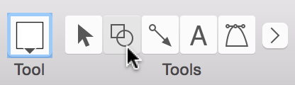
The most basic way to create a shape is with the Shape tool. Select the Shape tool in the toolbar (note, this tool might look different if you have changed its style).
With the Shape tool selected, drag across the canvas until you have a shape that is the size you want. It doesn’t have to be perfect right now; to set an exact size, use the Geometry object inspector (Command–1).

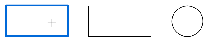
When you draw a shape, the mouse pointer changes to a set of crosshairs. The shape you draw takes on the Current Style in the Style Well. The default is a white-filled box with a simple black stroke. Click and drag to draw the shape; as you do, you’ll see a little box appear that gives you the dimensions of the object you’re drawing. Hold down the Shift key while drawing to restrain the dimensions of the shape to get that perfect square or circle you’ve been striving for.
Selecting, Resizing, and Moving Objects
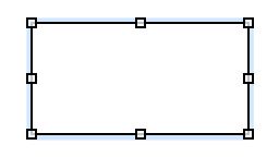
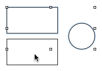
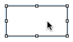
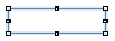
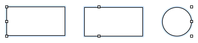
To select an object, first make sure you are using the Selection tool ( ), and then click the object. When the object is highlighted—and if it can be resized—you will see eight handles along its edges.
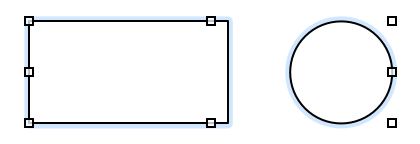
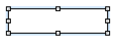
If you have selected two or more objects, the area of the selected objects receives the eight resizing handles. This allows you to position objects on the canvas first, and then later resize select objects as needed.
Once you have selected an object, you can modify it with the Inspectors or use the menu commands to alter its appearance.
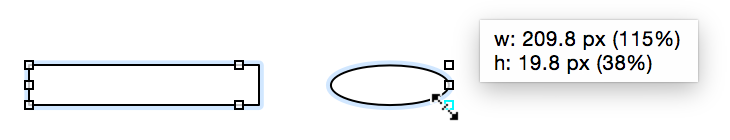
- To resize an object, first select the object and then drag one of its resizing handles until the object is the size you’d like.
- To select or deselect more objects without losing the selection you’ve already made, hold Command as you click other objects.
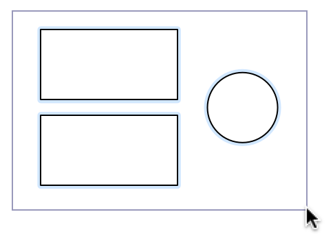
- To select several adjacent objects at once, click in an empty area of the canvas and drag a box around the objects that you want to select. If you hold down the Option key while dragging, you’ll get only the objects that fit completely inside the selection rectangle.
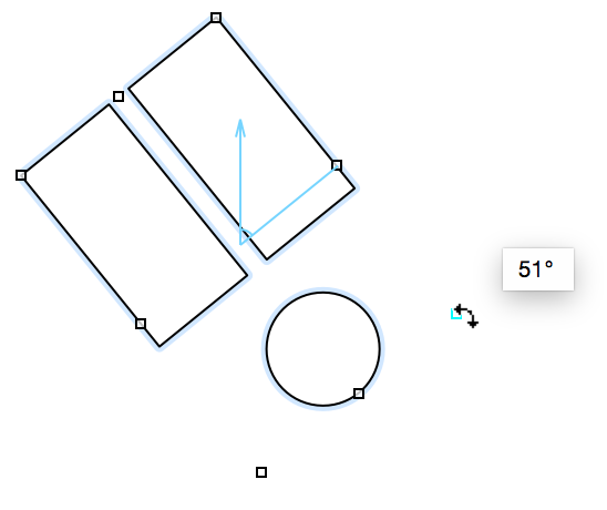
- To rotate an object, hold down the Command key while mousing over one of the eight handles. The pointer changes from a standard resizing control to a curved one. An angle control appears inside of the object, along with a helper dialog that shows the degree of the angle.
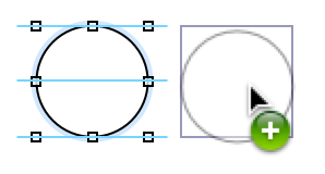
- To quickly create a copy of an object you’ve drawn, hold down the Option key and then click on and drag the object you would like to copy. An exact duplicate appears on the canvas; this method is much faster than using Copy and Paste from the Edit menu or their respective keyboard shortcuts.
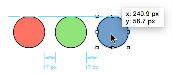
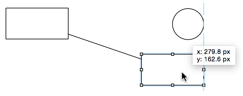
- To move an object, use the Selection tool to click and hold on the object, and then drag it to its new location. Smart Alignment Guides (the light blue lines) appear to help you align objects to one another, while Smart Distance Guides appear beneath the objects so you can space them evenly.
To group several objects together so they can be moved or styled as a single unit, select all of the objects and choose Arrange ▸ Group (Shift-Command-G).
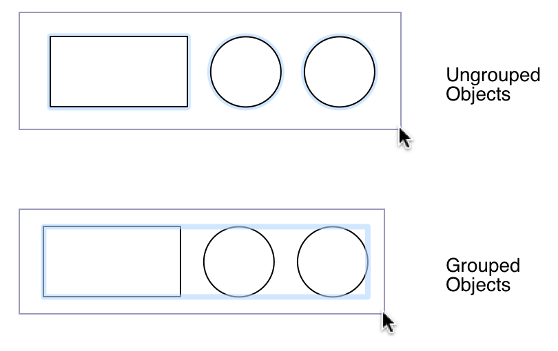
A group behaves like a single object; you can select it, move it around, resize it, use inspectors to change its style and properties, connect lines to it, and so on. Any objects can be grouped, even groups.
Click once to select the group as a whole, then click again to select an individual member of the group. You can keep clicking to select members of groups within groups.
To take a group apart, select it and choose Arrange ▸ Ungroup (Shift-Command-U).
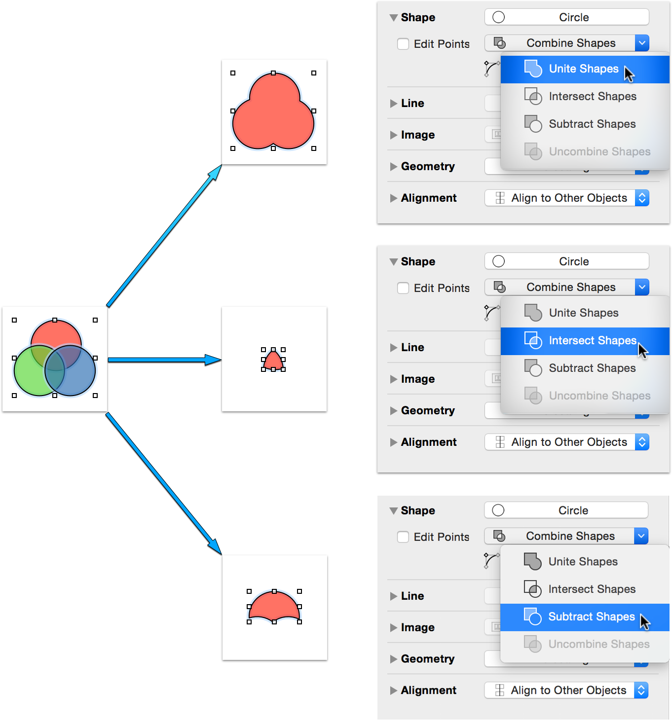
- (Pro) To combine two or more objects—for example, a circle that overlaps a rectangle—to create a unique shape, select the objects and then use the Shapes Object inspector (Command–1) to combine the shapes.
Connecting Objects with Lines
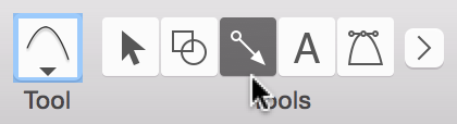
You can connect any two objects with the Line tool ( ).
).
- Select the Line tool. (Note, this tool might look different if you change its style.)
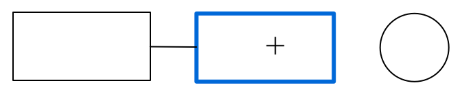
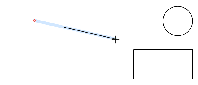
- Click the first object you would like to connect; this object becomes the source of the line. You’ll notice that when you move the mouse over the object, that a blue pulsing border appears around the object.
- Click the second object you would like to connect; this object becomes the destination of the line. When you drag the line from the first object to the next, you’ll notice that the blue pulsing border appears around the object you’re dragging the line to.
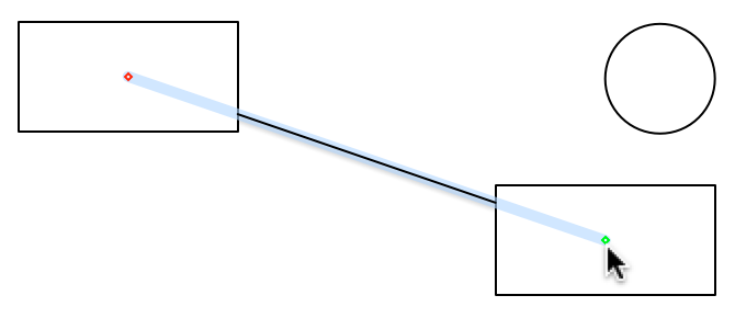
- When the objects are connected with a line, they stay connected no matter how much you change or move them around. That means the logical integrity of your diagram is preserved regardless of how you choose to style the objects.
- You can disconnect a line from an object by selecting the line and then dragging one of its end points. To delete the line, just select the line and press Delete.
Editing Objects
Any attribute of an object can be changed using the Object Inspectors; its size, shape, color, position, and so on. When you select an object, the applicable Inspectors become available in the right sidebar. Use the Inspector that deals with the attribute you want to change. As you change the settings in the inspector, the object changes on the canvas.
For example, let’s say that you want to change the Fill color inside of that boring white object you’ve just created:
- Select the object on the canvas.
- Select the Object Inspector (Command–1) in the right sidebar.

Open the Fill inspector. At the top of the inspector, you’ll find the Fill type pop-up menu, and the Fill color pop-up menu is on the left. For now, let’s leave the Fill type set to Solid Fill, and select a color to fill the object with.
Clicking the arrows on the side of the Fill color control pops up a list of preset colors from which you can choose. However, if you click the little rectangle next to the little arrows, the Colors palette pops open.
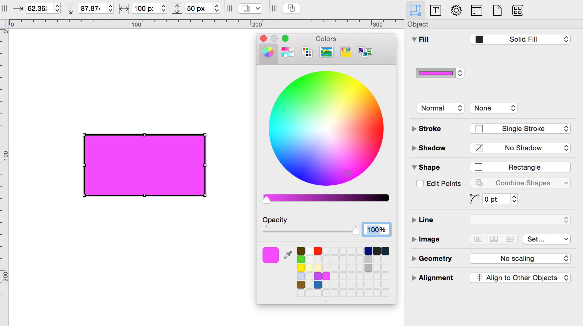
- Use the Colors palette to choose a color.
Tables (Pro)
A table is a special kind of group that organizes rows and columns of objects. To create a table:
- Create a single shape object to be the first cell of your table.
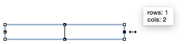
- With the object selected, choose Arrange ▸ Make Table (Shift-Command-T). Notice the grid-like handles on the top, bottom, left, and right sides of the object; this lets you know the object is a table.
- Drag the right-side table handle to the right to add columns.
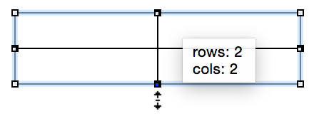
- Drag the bottom table handle down to add rows.
You can also select a number of already-existing objects and then choose Arrange ▸ Make Table; OmniGraffle rearranges the objects into rows and columns to the best of its ability.
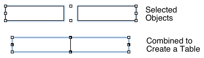
Table cells can be selected and edited just like group members. If you resize a cell, the rest of the cells in its row and column resize accordingly. When selecting cells, you can Shift-click to select everything between the cell you click and the last cell you selected.
You can add or remove rows or columns at any time by dragging the table handles outward or inward. Resize the table as a whole by dragging the ordinary corner handles. Use the Edit ▸ Tables commands when working within table cells to insert or select rows and cells.
To dismantle a table, select it and choose Arrange ▸ Ungroup (Shift-Command-U).
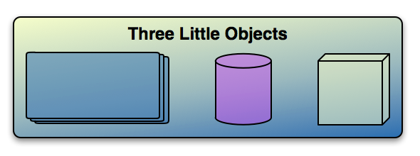
Subgraphs (Pro)
A subgraph is a special kind of group that can be expanded to show the hierarchy inside it, or collapsed to make it a single compact object. To create a subgraph:
- Select some objects on the canvas.
- With the objects selected, choose Arrange ▸ Group as Subgraph. Your objects are enclosed by a subgraph rectangle.
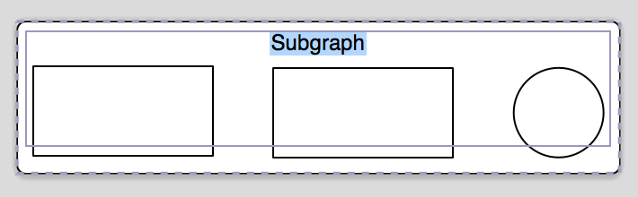
- Style and label the enclosing rectangle however you like.
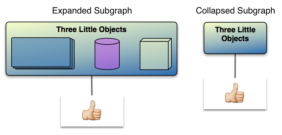
To collapse a subgraph, select it and then choose Arrange ▸ Collapse Subgraph (or from the contextual menu that appears when you Control-click the subgraph). The objects contained in the subgraph are hidden away, and the subgraph becomes a single object. Any incoming or outgoing connection lines belonging to objects in the subgraph become incoming or outgoing lines of the collapsed object itself.
Subgraph members can be selected and edited just like group members: click once to select the subgraph, then click again to select a member inside.
You can resize the containing rectangle, as long as you don’t make it too small to contain its member objects.
To disassemble a subgraph, select it and choose Arrange ▸ Ungroup (Shift-Command-U).
Smart Arrows
Finally, the various arrow shapes in OmniGraffle 6 have some smart behavior, whether they are connecting shapes or not.
When you change the point size of the line—say from 1 pt to 2 pts—the arrow scales with the point size of the line.
However, if all you want is a bigger arrow, you can adjust the size of the arrow using the scale field beneath the line tail or head pop-up menus. The scale fields accept positive and negative numbers, so you can have teeny-tiny or really huge arrows.
Working with Bézier Curves
OmniGraffle isn’t just for creating flow charts and diagrams; it’s a full-blown illustration app. With a little practice, you can quickly master drawing complex shapes in OmniGraffle. And once you have those beautiful things on your Canvas, you can use the Inspectors to style objects to your liking.
Before going any further, there are some basic things that you need to know to better work with Bézier curves in OmniGraffle.
Bézier Basics
Bézier curves introduce an entirely different lingo that you might not be familiar with, so we thought it best to introduce you to these concepts. Essentially, there are three bits to a Bézier curve: the Path, a Vector Point, and the curve’s Control Handles. Let’s take a closer look at these...
- The Path
- The Bézier curve itself is commonly referred to as the “path”. This is the bendy, curvy line which is made up of one or many Bézier curves.
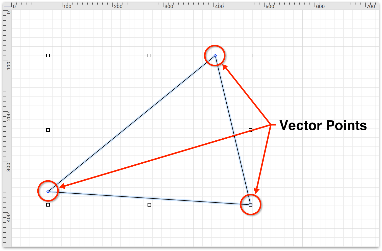
- Vector Points
- The point on a line that acts as the center for a Bézier curve is known as the vector point. Vector points appear as blue squares (or diamonds, depending on the angle of the curve).
If the shape you are working on has a vector point that’s wedged behind one of the eight handles on the shape’s bounding box, there’s a little trick to getting at it.
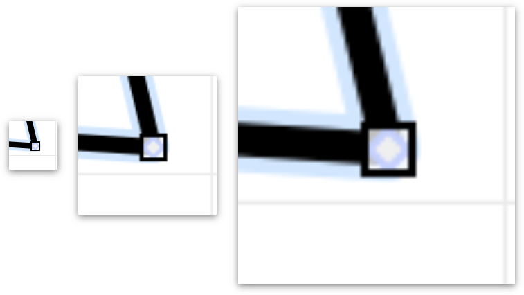
As you can see in the previous sequence of zoomed images, the vector point that you need to interact with is there—it’s just tucked behind the bounding box handle—so how do you get to it?
The secret is to hold down the Option and Command keys, and then single-click on the vector point. This selects the vector point so you can work on the shape without the bounding box handles getting in your way. Watch the following clip to see how this works:
To add a vector point to a path, double-click the path to add that point. To remove a vector point from a path, click to select the vector point, and then press Delete.
You can add as many vector points as you’d like to a path (as long as all of them fit, of course).
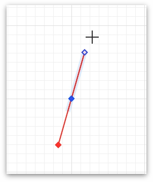
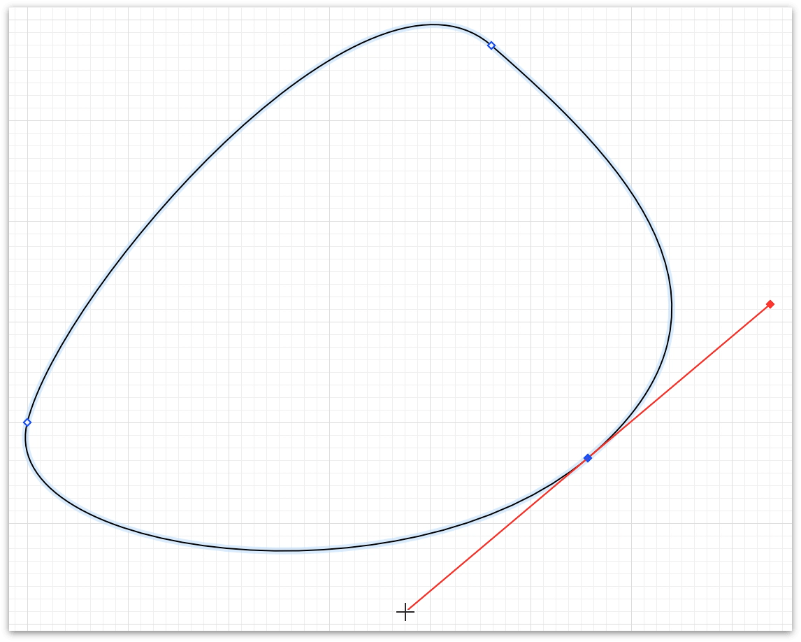
- Control Handles
- To create the Bézier curve, each vector point has a pair of red Control Handles that extend outward from the vector point. When you have a joint, where two straight paths meet at a vector point, that you want to convert to a Bézier curve, do one of the following:
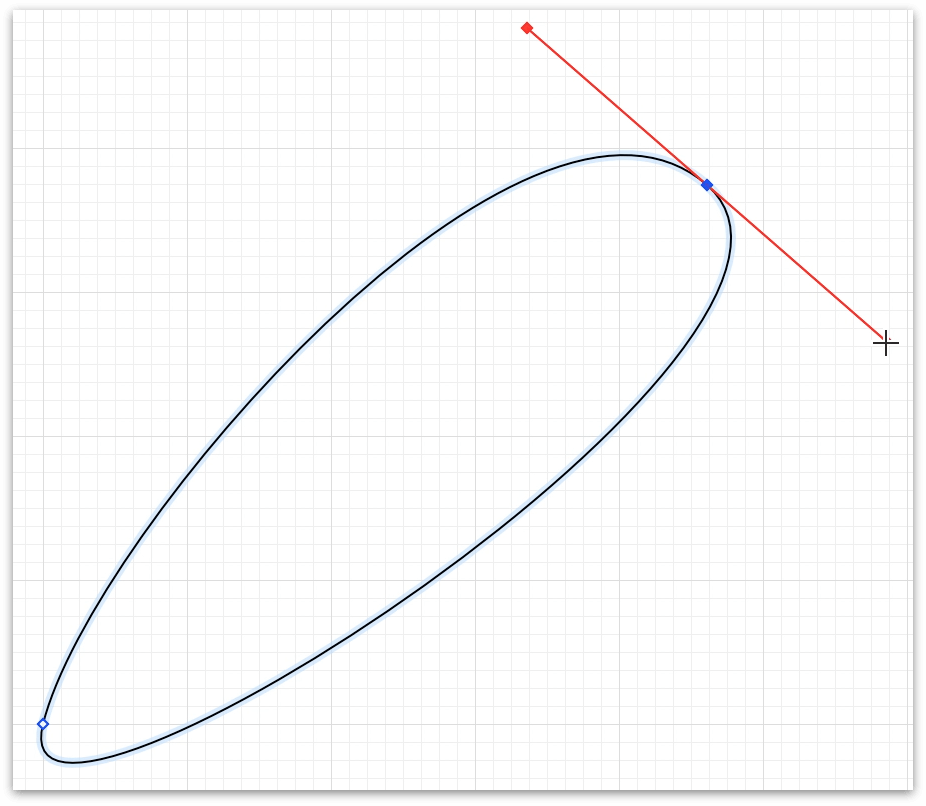
- When you Command-Click-Drag, opposing Control Handles extend from each side of the vector point.
- When you Option-Command-Click-Drag, only one Control Handle extends from the vector point in the direction you drag the mouse. This creates an obtuse curve. If you later decide that you want the other control handle to complete the curve, press Option-Command and then click the vector point and drag in the opposite direction from the existing control handle.
Another option for getting the second Control Handle to reveal itself is to hold down the Shift key, and then drag the Control Handle toward and through the vector point. Once you pass the vector point, both Control Handles appear.
- When you Command-Click-Drag, opposing Control Handles extend from each side of the vector point.
When working with the Control Handles, there are some additional key controls you can use to create the curve you need; these include:
- Shift: Holding the Shift key rotates the Control Handles around the vector point in 45° increments.
- Option: Holding the Option key lets you interact with one Control Handle at a time. This allows you to create complex curves by manipulating the individual handles.
- Shift-Option: Combining the Shift and Option keys when dragging a Control Handle restricts movement of the handle you’ve grabbed onto, and limits its rotation around the vector point to 45° increments.
Note
Control Handles, once made available along a path, cannot be deleted. If you try to delete a Control Handle, you’ll end up deleting the vector point, which is probably not what you want.
If your objective is to “remove” the Bézier curve based on that vector point, click and drag one of the handles toward the vector point. The Control Handles will “disappear” on their own once the crosshairs are close enough to the vector point.
Using the Pen Tool to Create a Bézier Shape
This quick tutorial shows you how to draw a shape using the Pen Tool, which you’ll turn into a leaf. Just follow along…
- Choose File ▸ Resource Browser (Shift-Command-N).
- Under Templates, choose Imperial Units and then select Auto-Resizing and click New Document.
Now it’s time to draw a blobby shape on the Canvas. Start by selecting the Pen Tool
 in the toolbar, and then follow these steps:
Click-and-drag to create the first vector point and its curve. As you drag the mouse away from where you clicked, you’ll notice that red Bézier control handles extend from the curve’s vector point. Don’t worry about these just yet; you will see how to use them later.
Move the mouse over and then click-and-drag to create the second vector point of the triangle and its curve.
Move the mouse down and then double-click-and-drag to create the third and final vector point of the curve. The double-click-drag is your way of telling OmniGraffle, “Hey, this is the final point. And, oh yeah, make it a curve, too.”
When you let go of the mouse button (or trackpad, depending on how you roll), OmniGraffle turns off the Pen Tool to stop you from adding additional vector points to the shape.
Watch the following video to see how to draw a Bézier shape with the Pen Tool:
You now have a rather blobby-looking shape on the Canvas. And we’re sure that you’re thinking, “How in the heck am I going to turn that into a leaf?!”.
It’s going to take some effort, and a little bit of fine-tuning, to turn that shape into a leaf. Here are some pointers:
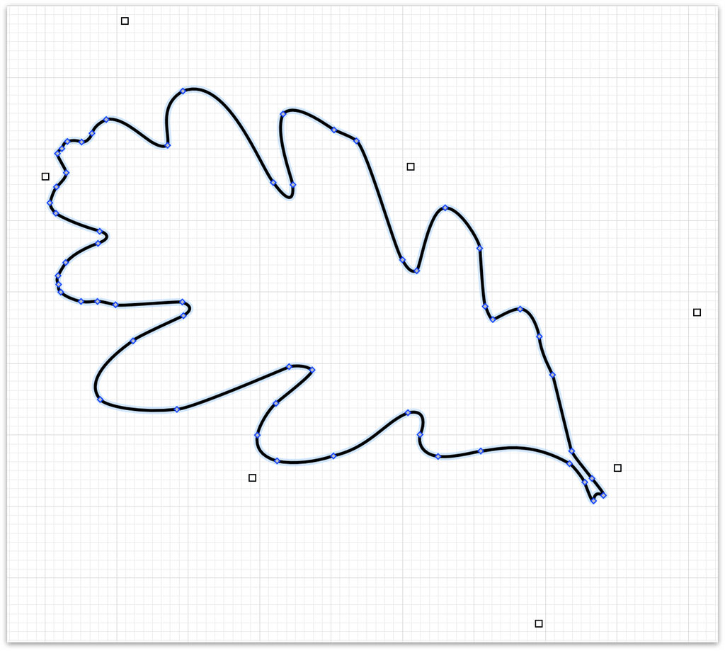
Start by adding more vector points to the path and drag them around so your leaf starts to take shape.
Use Command-drag to add the Control Handles to the vector points.
Experiment with Option-dragging individual Control Handles to widen the swoop of, or tighten, a curve.
Double-click between the vector points to add more, if needed. Or, if you find that a vector point isn’t necessary, click to select that point and press Delete to clear it from the path.
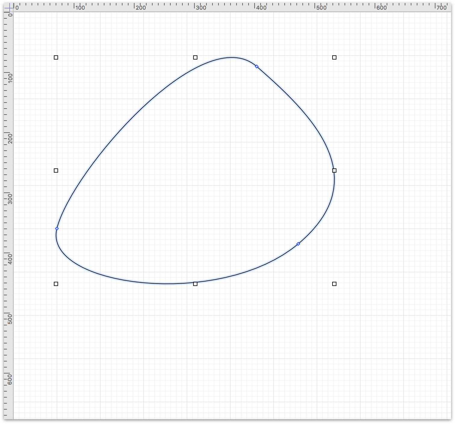
Finally, after a little work, the outline for your leaf can look something like this:
And with a little more work, your leaf can look like the following:
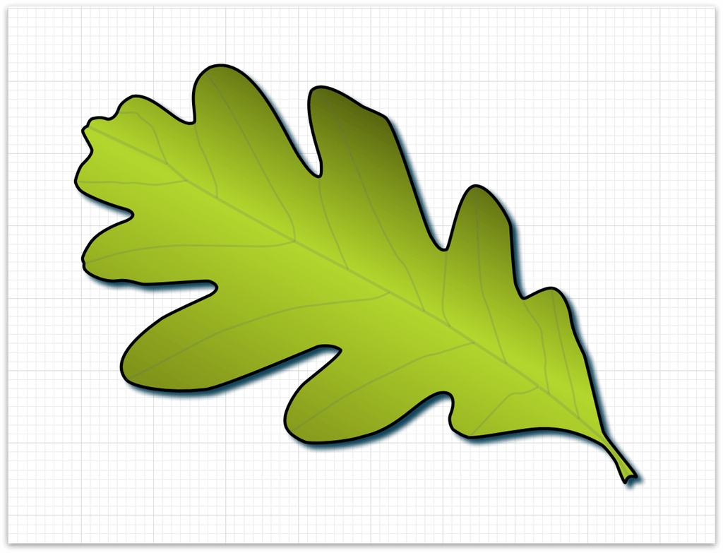
Some of the tools and inspectors you’ll need include:
Select the outline of the leaf and choose Edit ▸ Magnets ▸ Positions and set it so there are magnets at each vertex (i.e., vector point). This makes it so the points that form the bounds of the leaf can be used as anchor points for the veins of the leaf.
If you have OmniGraffle Pro, you can do the same thing with the Connections inspector.
- Use the Line tool to create the spine and veins.
- Use the Stroke inspector to vary the point size of the lines.
- Use the Stroke inspector to change the style of the leaf edge to Freehand.
- Use the Fill inspector to apply a Double Linear Gradient to the leaf.
- Use the Gradient Direction dial in the Fill inspector to adjust the gradient’s centerline so that it matches the path of the leaf’s spine.
- Use pinch gestures to zoom in and out on the Canvas while connecting the spine and veins to each other and to the magnets (i.e., vector points) of the leaf.
And, if you create something really cool that you think other OmniGraffle users could enjoy, don’t forget that you can submit it as a stencil to Stenciltown.